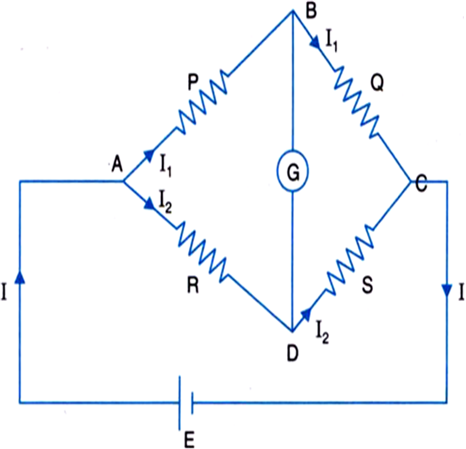
Applying Kirchhoff’s second law for mesh ABCD,
I1P – I2R = 0
or, J1P = I2R ...(i)
For mesh BCDB,
I1Q – I2S = 0
or, I1Q = I2S ...(ii)
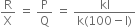
Dividing (i) by (ii), we get
This is the balanced condition of the Wheatstone bridge.
Measurement of specific resistance: Slide wire or meter bridge is a practical form of Wheatstone bridge.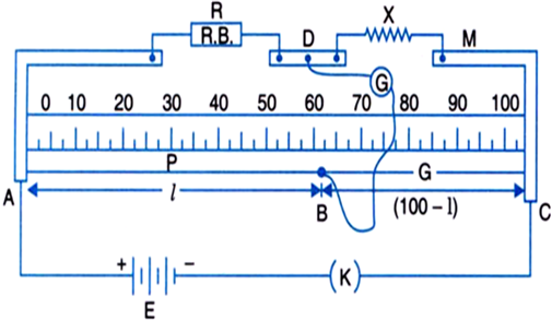
In the figure X is unknown resistor and R.B is resistance box. After inserting the key k, jockey is moved on wire AC till galvanometer shows no deflection (point B). If k is the resistance per unit length of wire AC.
P = resistance of AB = kl
Q = resistance of BC = k(100 - l)
or, 
If r is the radius of wire and l be its length, then its resistivity will be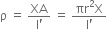
Precautions: (i) The null point should lie in the middle of the wire.
(ii) The current should not be allowed to flow in the wire for a long time.
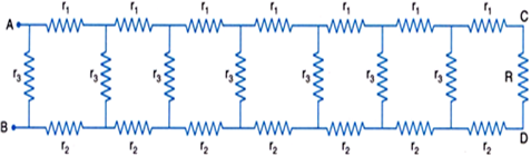
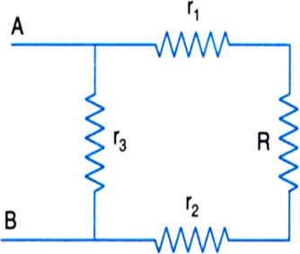
Let us consider the extreme right square of the loop.
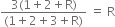
Resistance across EF = (r1 + R + r2) and r3 in parallel
This value should be equal to R, so that by the repeated operation of this type will be left with only one square which will be the left extreme one and it will have a value R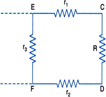
i.e., 
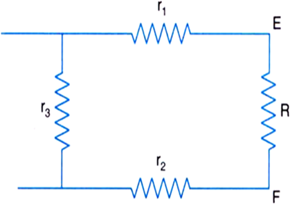
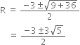
Substituting the numerical values
or, 

or, 

Let x be the number of cells in series in each row and let there be y such rows in parallel.
Total number of cells = xy = 24
Resistance of each row in series = 2x ohms
Total internal Resistance due to all xy batteries = R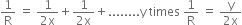
Total internal resistance  ohms (because there are y rows in parallel)
The maximum current passes through the circuit when the internal resistance of the battery of cells equals the external resistance.
Thus, 
or, 
But 
Hence, 
i.e., there should be two rows of 12 cells in series (see the figure below). The current in the circuit is
I = 
Because of two rows have the same resistance, the current in each arm must be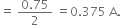
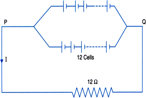
Therefore, current through each cell = 0.375 A
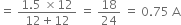
The potential difference across the external resistance is
= 12 x 0.75 = 9 V
Let,
l1, l2, and l3 be lengths of three copper wires.
D1, D2 and D3 be their diameters and,
A1, A2, A3 be their area of cross section.
Given,
l1: l2: l3 = 2: 3: 4
i.e., l1 = 2 l, l2 = 3 l and l3 = 4 l.
Also, given,
D1: D2: D3 = 4: 5: 6
∴ A1: A2:A3 = (4)2: (5)2: (6)2 = 16: 25: 36
That is,
A1 = 16 A, A2 = 25 A and A3 = 36 A
If ρ is the resistivity of copper, then
and,
or
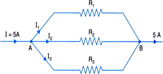
Let I1, I2 and I3 be the currents through the wires of resistances R1, R2 and R3 respectively. Then,
...(i)
and,
and,
Putting these values in equation (i) we get,
I1 + 1.04 I1 + 1.125 I1 = 5
on solving, we get
I1 = 1.58 A
I2 = 1.04 x 1.58 = 1.64 A
and,
I3 = 1.125 x 1.58 = 1.78 A.
A potentiometer wire of length 1 m is connected to a driver cell of emf 3 V as shown in the figure. When a cell of 1.5 V emf is used in the secondary circuit, the balance point is found to be 60 cm. On replacing this cell and using a cell of unknown emf, the balance point shifts to 80 cm.
(i) Calculate unknown emf of the cell.
(ii) Explain with reason, whether the circuit works, if the driver cell is replaced with a cell of emf 1V.
(iii) Does the high resistance R, used in the secondary circuit affect the balance point? Justify your answer.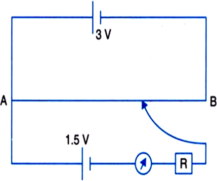
Given,
Length of the potentiometer wire, l = 1 m
Emf of the driver cell , E = 3 V
Emf of the cell in the secondary circuit, E = 1.5 V
Balance point obtained, l1 = 60 cm= 0.60 m
Now,
On replacing the cell by a cell of unknown emf, the balance point obtained is at, l2 = 80 cm = 0.80 m
(i) By using the formula,
Hence, the unknown emf is found to be 2V.
(ii) The circuit will not work.
Reason: Because there will be smaller fall of potential across the potentiometer wire as compared to the emf of the cell in secondary circuit to be determined. Hence, the balance point will not be obtained on the potentiometer wire.
Thus, the condition for obtaining the balance point is that, the emf of the driver cell should be greater than the emf of the cell to be determined.
(iii) High resistance R, used in the secondary circuit does not affect the balance point because, at balance point the galvanometer shows no deflection implying the absence of current in this condition.


 Switch


