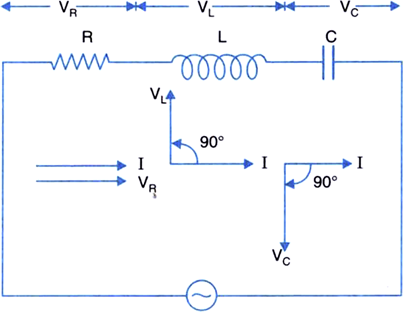
An a.c. source of voltage V = Vm sin ωt is connected, one-by-one, to three circuit elements X, Y and Z. It is observed that the current flowing in them,
(i) is in phase with applied voltage for element X.
(ii) lags the applied voltage, in phase, by /2 for element Y.
(iii) leads the applied voltage, in phase, by /2 for element Z. Identify the three circuit elements.
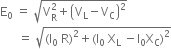
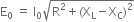
Find an expression for the (a) current flowing in the circuit, (b) net impedance of the circuit, when the same a.c. source is connected across a series combination of the elements X, Y and Z. (c) If the frequency of the applied voltage is varied, set up the condition of frequency when the current amplitude in the circuit is maximum. Write the expression for this current amplitude.
 (For R)
 (For L)
 ) (For C)

 is represented along OX.
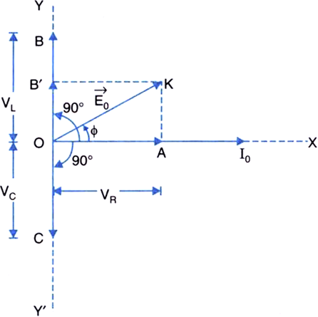
 is in phase with current, it is represented by the vector
  salong OX.
 along OY, 90° ahead of

 rotated clockwise through 90° from the direction of
 is along OY' is along OY'.
 assuming that
 The resultant of the resultant of
  and
and  is the diagonal
  of the rectangle OAKB'. Hence the vector sum of
  is phasor
  represented by
  making an angle
  with current phasor