Draw a circuit diagram of a transistor amplifier in CE configuration. Define the terms:(i) Input resistance and (ii) Current amplification factor. How are these determined using typical input and output characteristics? - Zigya
Advertisement

Draw a circuit diagram of a transistor amplifier in CE configuration.

Define the terms:
(i) Input resistance and
(ii) Current amplification factor. How are these determined using typical input and output characteristics?


The circuit diagram of a transistor amplifier in CE configuration is given by, 
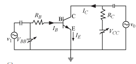
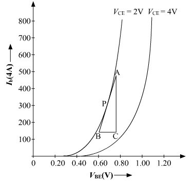


Input resistance-: 

a)The ratio of change in base-emitter voltage to base current gives us the input resistance. We can calculate change in VBE and change in IB from the input characteristics. To find the input resistance, mark a point P on the input characteristic. Draw a tangent at point P. The reciprocal of slope AB will give us the input resistance. 


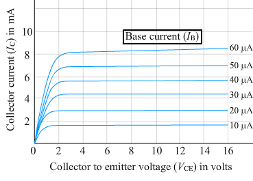
b) Current amplification factor: It is defined as the ratio of change in collector current to the change in base current. Output characteristics will help to calculate the current amplification factor.

1237 Views

Advertisement

Semiconductor Electronics: Materials, Devices and Simple Circuits

Hope you found this question and answer to be good. Find many more questions on Semiconductor Electronics: Materials, Devices and Simple Circuits with answers for your assignments and practice.

Physics Part II

Browse through more topics from Physics Part II for questions and snapshot.