The curves which are used to represent the magnetic field, such that the number of lines represent the strength of the magnetic field at any point are called magnetic lines of force. The direction of magnetic force is given by the tangent of the curve at any point.
Properties of magnetic lines of force:
(i) These are closed curves which move from the N-pole to the S-pole and then return to the N-pole through the interior of the magnet.
(ii) No two magnetic lines of force can intersect each other.
(iii) Magnetic lines are continuous curves and they tend to contract longitudnally and expand laterally. This implies, attraction between unlike poles and repulsion between like poles.
(v) The relative closeness of the lines of force gives a measure of the strength of the magnetic field. It is found the magnetic strength is maximum at the poles.
(i) A current carrying conductor has a magnetic field associated with it. The two magnetic fields, one due to the magnet and the other due to the current in the conductor, interact. This produces a force on the conductor.
(ii) The direction of the magnetic force depends on
(a) the strength of electric current, and
(b) the strength of the magnetic field.
(iii) Fleming’s left hand rule is used for determination of the direction of magnetic force on a current carrying conductor.
(iv) Fleming’s left hand rule: Stretch the forefinger, the central finger and the thumb of the left hand mutually perpendicular to each other. If the forefinger points in the direction of the magnetic field, the central finger in the direction of current, then the thumb. points in the direction of force on the conductor.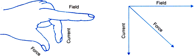
What is an electromagnet? On factors does the strength of an electromagnet depend?
Or
What is an electromagnet? Draw a circuit diagram to show how a soft iron piece can be transformed into an electromagnet.
Electromagnet: A soft iron core placed inside a solenoid behaves like a powerful magnet when a current is passed through the solenoid. This device is called an electromagnet. When the current is switched off, the iron core loses its magnetism and so it is no longer an electromagnet. Thus, electromagnets are temporary magnets.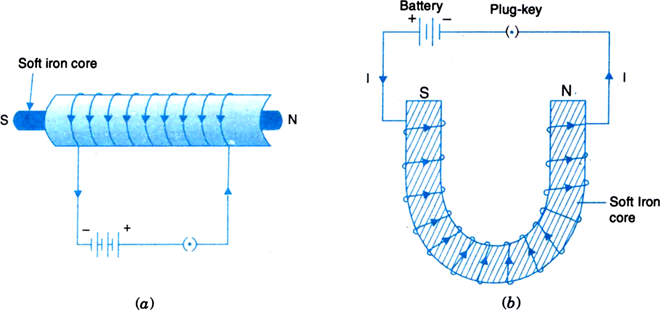
Fig. Electromagnet (a) Bar type (b) Horse-shoe type
Factors on which the strength of an electromagnet depends:
(i) Number of turns in the coil: The larger the number of turns in the coil, greater is the strength of the electromagnet.
(ii) Strength of the current: The larger the current passed through the solenoid, more powerful is the electromagnet.
(iii) Nature of the core material: The core of the magnetic material like soft iron increases the strength of the electromagnet.
AC. Generator: It is a device which converts mechanical energy into alternating form of electrical energy.
Principle: It works on the principle of electromagnetic induction. When a closed coil is rotated in a uniform magnetic field with its axis perpendicular to the magnetic field, the magnetic field lines passing through the coil change and an induced emf and hence a current is set-up in it.
Construction: It consists of the following main parts:
1. Field magnet: It is a strong horse shoe-type permanent magnet with concave poles.
2. Armature: ABCD is a rectangular armature coil. It consists of a large number of turns of insulated copper wire wound on a soft iron cylindrical core. It can be rotated about an axis perpendicular to the magnetic field of the field magnet.
3. Slip rings: These are two brass rings S1 and S2 rigidly connected to the two ends of the armature coil. As the coil rotates, slip rings also rotate about the same axis of rotation.
4. Brushes: These are two graphite rods B1 and B2 which are kept pressed against the slip rings S1 and S2. Through these brushes, the current induced in the armature coil is sent to the external circuit.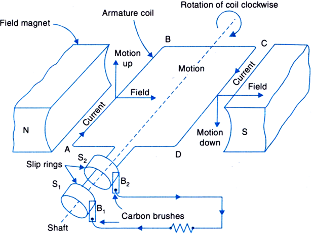
Fig. A.C. generator
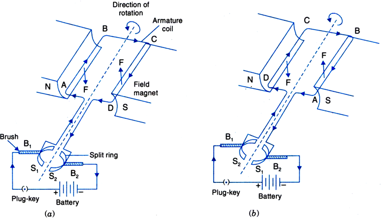
Working: As shown in Fig, suppose the armature coil ABCD is in the horizontal position. Now the coil is rotated clockwise. The coil cuts the magnetic lines of force. The arm AB moves upwards while the arm CD moves downwards. According to Fleming’s right hand rule, the induced current flows from A to B in arm AB and C to D in arm CD i.e., the induced current flows along ABCD. The induced current flows in the circuit through brush B2 to B1.
After half the rotation of the armature, the arm CD moves upwards and AB moves downwards. The induced current now flows in the reverse direction i.e., along DCBA. The current flows from B1 to B2. Thus the direction of current in the external circuit changes after every half rotation. Such a current which changes its direction after equal intervals of time is called alternating current. This device is called A.C. generator.


 Switch


