Multiple Choice Questions
The temperature dependence of resistances of Cu and undoped Si in the temperature range 300-400 K is best described by:
Linear increase for Cu, linear increase for Si.
Linear increase for Cu, exponential increase for Si.
Linear increase for Cu, exponential decrease for Si.
Linear increase for Cu, exponential decrease for Si.
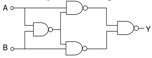
If a, b, c, d are inputs to a gate and x is its output, then, as per the following time graph, the gate is: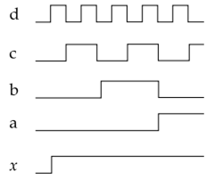
NOT
AND
OR
OR
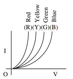
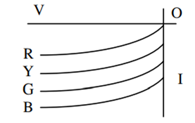
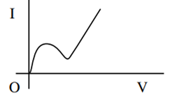
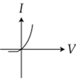
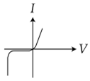
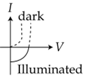
Identify the semiconductor devices whose characteristics are given below, in the order (a), (b), (c), (d):
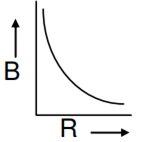
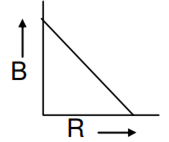
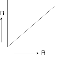
A charge Q is uniformly distributed over the surface of non conducting disc of radius R. The disc rotates about an axis perpendicular to its plane and passing through its centre with an angular velocity ω. As a result of this rotation, a magnetic field of induction B is obtained at the centre of the disc. If we keep both the amount of charge placed on the disc and its angular velocity to be constant and vary the radius of the disc than the variation of the magnetic induction at the centre of the disc will be represented by the figure
In a common emitter amplifier circuit using an n-p-n transistor, the phase difference between the input and the output voltages will be
135°
180°
45°
45°
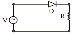
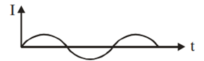
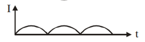
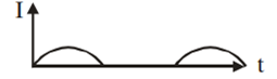
A p–n junction (D) shown in the figure can act as a rectifier. An alternating current source (V) is connected in the circuit.