 Multiple Choice Questions
A resistance 'R' draws power 'P' when connected to an AC source. If an inductance is now placed in series with the resistance such that the impedance of the circuit becomes 'Z' the power drawn will be


A small signal voltage V(t) = Vo sin  is applied across an ideal capacitor C:
over a full cycle the capacitor C does not consume any energy from the voltage source
current I(t) is in phase with voltage V(t)
Current I(t) leads voltage V(t) by 180o
Current I(t) leads voltage V(t) by 180o
A.
over a full cycle the capacitor C does not consume any energy from the voltage source
For an ac circuit containing capacitor only, the phase difference between current and voltage will be  (i.e., 90o).
In this case, the current is ahead of voltage by 
Therefore, power is given by,
P = VI cos 
where,  is the phase difference between voltage and current.
P = VI cos 90o = 0
An inductor of 20 mH, a capacitor of 50  and a resistor of 40 ohm are connected in series across a source of emf V = 10 sin 340 t. the power loss in the ac circuit is,
0.67 W
0.76 W
0.89 W
0.89 W
The instantaneous values of alternating current and voltages in a circuit are given as
The average power in Watts consumed in the circuit is
1/4

1/2
1/2
If voltage across a bulb rated 220 V -100W drops by 2.5% of its rated value, the percentage of the rated value by which the power would decrease is
20%
2.5%
5%
5%
A transformer having efficiency of 90% is working on 200 V and 3 kW power supply. If the current in the secondary coil is 6 A, the voltage across the secondary coil and the current in the primary coil respectively are:
300 V, 15 A
450 V, 15 A
450 V, 13.5 A
450 V, 13.5 A
In an AC circuit, an alternating voltage  100t volt is connected to a capacitor of capacity 1μF. The rms value of the current in the circuit is
100 mA
200 mA
20 mA
20 mA
An AC voltage is applied to a resistance R and an inductor L in series. If R and the inductive reactance are both equal to 3Ω, the phase difference between the applied voltage and the current in the circuit is
π/4
π/2
zero
zero
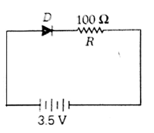
In the given figure, a diode D is connected to an external resistance R = 100 Ω and an e. m. f of 3.5 V. If the barrier potential developed across the diode is 0.5 V, the current in the circuit will be 
30 mA
40 mA
20 mA
20 mA
